FDM_1D_verticalコマンドの検証

2. 水平2層構造での計算

(Validation of FDM_1D_vertical command; 2. Calculation in a two-layer stratified medium)


問題設定 (Problem setting)

地震波速度\(V_1\)、厚さ\(d\)の均質媒質の層の下に 地震波速度\(V_2\)の半無限均質媒質がある 水平2層構造を考える。 地表面の標高を\(z=0\)とする。 このとき層境界の標高は\(z=-d\)となる。 この層境界に鉛直下方から最初に入射した波を \[\begin{equation} V_{0,u}(-d-0,t)=f(t) \label{eq.V_0_u.boundary} \end{equation}\] とする。なお以下では反射・透過の回数を1つ目の添字(数字)で表し、 2つ目の添字は上向き伝播(u)、下向き伝播(d)の区別を表すものとする。
Let us consider a two-layer horizontally stratified medium, composed of a uniform medium of seismic wave velocity \(V_1\) and thickness \(d\) underlain by a homogeneous half space of seismic wave velocity \(V_2\). Let the ground surface altitude be \(z=\). Then the altitude of the layer boundary is \(z=-d\). Let the first incident wave from below at this layer boundary be represented by Eq. (\ref{eq.V_0_u.boundary}). Hereafter, the total number of reflection and transmission is represented by the 1st subscript (number), while the 2nd subscript distinguishes upward (u) and downward (d) propagating waves.

\(V_{0,u}\)は\(z=-d\)の層境界で反射波(下向き)と透過波(上向き)に分離する。 密度が一様と仮定した場合、反射係数は\((V_2-V_1)/(V_2+V_1)\)、 透過係数は\(2V_2/(V_2+V_1)\)であるので、反射波は \[\begin{equation} V_{1,d}(-d-0,t)=\frac{V_2-V_1}{V_2+V_1}f(t) \label{eq.V_1_d.boundary} \end{equation}\] 透過波は \[\begin{equation} V_{1,u}(-d+0,t)=\frac{2V_2}{V_2+V_1}f(t) \label{eq.V_1_u.boundary} \end{equation}\] となる。この透過波が地表に到達するときには走時\(d/V_1\)だけ遅れるので \[\begin{equation} V_{1,u}(0,t)=\frac{2V_2}{V_2+V_1}f(t-d/V_1) \label{eq.V_1_u.surface} \end{equation}\] となる。この波は地表で反射して反射波 \[\begin{equation} V_{2,d}(0,t)=\frac{2V_2}{V_2+V_1}f(t-d/V_1) \label{eq.V_2_d.surface} \end{equation}\] を生成する。この反射波は鉛直下方へと伝播し、層境界では \[\begin{equation} V_{2,d}(-d+0,t)=\frac{2V_2}{V_2+V_1}f(t-2d/V_1) \label{eq.V_2_d.boundary} \end{equation}\] となる。
The wave \(V_{0,u}\) reduces to reflected (downward) and transmitted (upward) waves at the layer boundary \(z=-d\). The reflection and transmission coefficients are \((V_2-V_1)/(V_2+V_1)\) and \(2V_2/(V_2+V_1)\), respectively, if the density is assumed to be uniform. Then the reflected and transmitted waves are denoted by Eqs. (\ref{eq.V_1_d.boundary}) and (\ref{eq.V_1_u.boundary}), respectively. This transmitted wave arrives the ground surface after a travel time \(d/V_1\), giving Eq. (\ref{eq.V_1_u.surface}). This wave reflects at the ground surface, generating a reflected wave given by Eq. (\ref{eq.V_2_d.surface}). This reflected wave propagates downward, and the wave at the layer boundary is given by Eq. (\ref{eq.V_2_d.boundary}).

\(V_{2,d}\)は再び層境界で反射波と透過波に分離するが、 今回は上方からの入射であるので反射波が上向きで反射係数は\((V_1-V_2)/(V_1+V_2)\)、 透過波は下向きで透過係数は\(2V_1/(V_1+V_2)\)となる。 したがって反射波は \[\begin{eqnarray} V_{3,u}(-d+0,t) &=& \frac{2V_2}{V_2+V_1}\frac{V_1-V_2}{V_1+V_2}f(t-2d/V_1) \nonumber \\ &=& -\frac{2V_2(V_2-V_1)}{(V_2+V_1)^2}f(t-2d/V_1) \label{eq.V_3_u.boundary} \end{eqnarray}\] 透過波は \[\begin{eqnarray} V_{3,d}(-d-0,t) &=& \frac{2V_2}{V_2+V_1}\frac{2V_1}{V_1+V_2}f(t-2d/V_1) \nonumber \\ &=& \frac{4V_2V_1}{(V_2+V_1)^2}f(t-2d/V_1) \label{eq.V_3_d.boundary} \end{eqnarray}\] と表せる。この反射波\(V_{3,u}\)は地表に到着するまでに走時\(d/V_1\)だけ遅れて \[\begin{equation} V_{3,u}(0,t) =-\frac{2V_2(V_2-V_1)}{(V_2+V_1)^2}f(t-3d/V_1) \label{eq.V_3_u.surface} \end{equation}\] となり、地表で反射して反射波 \[\begin{equation} V_{4,d}(0,t) =-\frac{2V_2(V_2-V_1)}{(V_2+V_1)^2}f(t-3d/V_1) \label{eq.V_4_d.surface} \end{equation}\] を生成し、この反射波が層境界に到着するまでに更に走時\(d/V_1\)だけ遅れて \[\begin{equation} V_{4,d}(-d+0,t) =-\frac{2V_2(V_2-V_1)}{(V_2+V_1)^2}f(t-4d/V_1) \label{eq.V_4_d.boundary} \end{equation}\] となる。そして層境界で再び反射・透過して反射波 \[\begin{eqnarray} V_{5,u}(-d+0,t) &=& -\frac{2V_2(V_2-V_1)}{(V_2+V_1)^2}\frac{V_1-V_2}{V_1+V_2}f(t-4d/V_1) \nonumber \\ &=& \frac{2V_2(V_2-V_1)^2}{(V_2+V_1)^3}f(t-4d/V_1) \label{eq.V_5_u.boundary} \end{eqnarray}\] および透過波 \[\begin{eqnarray} V_{5,d}(-d-0,t) &=& -\frac{2V_2(V_2-V_1)}{(V_2+V_1)^2}\frac{2V_1}{V_1+V_2}f(t-4d/V_1) \nonumber \\ &=& -\frac{4V_2(V_2-V_1)V_1}{(V_2+V_1)^3}f(t-4d/V_1) \label{eq.V_5_d.boundary} \end{eqnarray}\] を生成する。
The wave \(V_{2,d}\) again reduces to reflected and transmitted waves again. However, in this case the incident wave comes from upward, meaning that the reflected wave goes upward with the reflection coefficient \((V_1-V_2)/(V_1+V_2)\), and the transmitted wave goes downward with the transmission coefficient \(2V_1/(V_1+V_2)\). Therefore the reflected and transmitted waves are represented by Eqs. (\ref{eq.V_3_u.boundary}) and (\ref{eq.V_3_d.boundary}), respectively. This reflected wave arrives at the ground surface after a travel time \(d/V_1\), giving Eq. (\ref{eq.V_3_u.surface}), and then reflects to generate a reflected wave expressed by Eq. (\ref{eq.V_4_d.surface}), which propagates to the boundary with a travel time \(d/V_1\) to give Eq. (\ref{eq.V_4_d.boundary}). Then at the layer boundary, a reflected wave (Eq. \ref{eq.V_5_u.boundary}) and a transmitted wave (Eq. \ref{eq.V_5_d.boundary}) are generated.

以後、同様のことが無限に繰り返される。 最初に層境界を透過した後、 地表と層境界での反射を計\(2n\)回繰り返した波(第1層を上向きに伝播) は層境界で \[\begin{equation} V_{2n+1,u}(-d+0,t) =(-1)^n\frac{2V_2(V_2-V_1)^n}{(V_2+V_1)^{n+1}}f(t-2nd/V_1) \label{eq.reflected.u.boundary} \end{equation}\] 地表で \[\begin{equation} V_{2n+1,u}(0,t) =(-1)^n\frac{2V_2(V_2-V_1)^n}{(V_2+V_1)^{n+1}}f(t-(2n+1)d/V_1) \label{eq.reflected.u.surface} \end{equation}\] となる。 また、最初に層境界を透過した後、 地表と層境界での反射を計\(2n+1\)回繰り返した波(第1層を下向きに伝播) は地表で \[\begin{equation} V_{2n+2,d}(0,t) =(-1)^n\frac{2V_2(V_2-V_1)^n}{(V_2+V_1)^{n+1}}f(t-(2n+1)d/V_1) \label{eq.reflected.d.surface} \end{equation}\] 層境界で \[\begin{equation} V_{2n+2,d}(-d+0,t) =(-1)^n\frac{2V_2(V_2-V_1)^n}{(V_2+V_1)^{n+1}}f(t-(2n+2)d/V_1) \label{eq.reflected.d.boundary} \end{equation}\] となる。 最初に層境界を透過した後、 地表と層境界での反射を計\(2n+1\)回繰り返し、 最後に層境界で透過して半無限媒質を下方に伝播する波は層境界で \[\begin{equation} V_{2n+3,d}(-d-0,t) =(-1)^n\frac{4V_2(V_2-V_1)^nV_1}{(V_2+V_1)^{n+2}}f(t-(2n+2)d/V_1) \label{eq.transmitted.d.boundary} \end{equation}\] となる。ここで\(n\geq 0\)とする。 \(V_{0,u}\)と\(V_{1,d}\)は (\ref{eq.reflected.u.boundary})-(\ref{eq.transmitted.d.boundary}) 式では表せず、別扱いが必要になる点に留意。
The same reflection and transmission are infinitely repeated. The wave which repeated a total of \(2n\) reflections at the ground surface and layer boundary after the first transmission at the layer boundary (which propagates upward in the 1st layer) is given by Eq. (\ref{eq.reflected.u.boundary}) at the layer boundary and (\ref{eq.reflected.u.surface}) at the ground surface. The wave which repeated a total of \(2n+1\) reflections at the ground surface and layer boundary after the first transmission at the layer boundary (which propagates downward in the 1st layer) is expressed by Eq. (\ref{eq.reflected.d.surface}) at the ground surface and (\ref{eq.reflected.d.boundary}) at the layer boundary. A wave which has experienced the first transmission at the layer boundary, followed by a total of \(2n+1\) reflections at the ground surface and layer boundary and a final transmission at the layer boundary to propagate downward in the half spece medium is represented as Eq. (\ref{eq.transmitted.d.boundary}) at the layer boundary. Here, \(n\geq 0\) is assumed. Note that \(V_{0,u}\) and \(V_{1,d}\) cannot be described by Eqs. (\ref{eq.reflected.u.boundary})-(\ref{eq.transmitted.d.boundary}); separate treatments are needed for them.

以下では適当な\(f(t)\)を与えてこれらの波を重ね合わせることで ボアホール観測点と地表での波形(正解)を合成する。 その上でボアホール観測点での合成波形を用いて差分法により地表での波形を計算し、 正解と一致するかを確かめる。 ボアホール観測点が層境界よりも浅部にある場合と深部にある場合に分けてテストする。
Below, a function \(f(t)\) is assumed and the waves expressed by the equations above are summed to synthetize the waveforms at the borehole station and ground surface (correct answers). Using the synthetized waveform at the borehole station, the waveform at the ground surface is simulated by the FDM, and the result is compared with the correct answer. The tests are conducted for the bore stations which are shallower and deeper than the layer boundary.

以下のテストでは\(V_1=2000\) m/s、\(V_2=5000\) m/sとする。 均質媒質でのテストにならって 観測波形の時間刻みは0.01 s、差分計算の空間刻みは\(\Delta z=0.2\) mとし、 \(f(t)\)として1周期cos関数を用いる。 また補間が悪さをしないように観測波形には20 Hzのローパスフィルターを掛ける。 地震波速度の最大値が\(V_{max}=5000\) m/sであるので 計算の安定条件は \(\Delta t<\Delta z/(\sqrt{3}V_{max})\sim 2.3\times 10^{-5}\) sであり、 \(\Delta t=2\times 10^{-5}\) sを用いる。 第1層の厚さは\(d\sim 1200\) mとする。 但し差分法のスキームの都合上、応力の定義点で地震波速度を定義できないと困るので 少しだけずらして\(d=1200.1\) mとする。 この場合、層境界と地表面の間の往復走時は\(2d/V_1\sim 1.2\) sであるので、 ある\(n\)に対応する反射波とその次の\(n\)に対応する反射波の間隔は1.2 sである。 十分な数の反射波が入るよう、計算する波形の長さは20 sとする。
In the test below, \(V_1=2000\) m/s and \(V_2=5000\) m/s are used. Based on the previous tests using a uniform medium, the observed waveform is sampled at 0.01 s, a spatial grid interval of \(\Delta z=0.2\) m for the FDM calculation is adopted, and one-cycle cosine function is used for \(f(t)\). To avoid the effects of interpolation, a low-pass filter of 20 Hz is applied to the observed waveform. At the maximum seismic wave velocity is \(V_{max}=5000\) m/s, the stability condition is \(\Delta t<\Delta z/(\sqrt{3}V_{max})\sim 2.3\times 10^{-5}\) s, and we use \(\Delta t=2\times 10^{-5}\) s. For the thickness of the first layer, \(d\sim 1200\) m is used; strictly, \(d=1200.1\) m is used to account for the requirement that the seismic wave velocity must be defined at the definition points of the stress in the FDM scheme. In this case, the round-trip travel time between the layer boundary and the ground surface is \(2d/V_1\sim 1.2\) s, indicating that the time interval of the reflected waves of two adjacent \(n\) values is 1.2 s. To ensure a sufficiently large number of reclected waves to be in the time window, a window length of 20 s is used.


2-1. ボアホール観測点が層境界よりも浅部にある場合 (Borehole station shallower than the layer boundary)

ボアホール観測点の深さを\(h\)(標高を\(z=-h\))とする。 \(h<d\)の場合を考える。 以下のテストでは\(h=1000.1\) mを用いる。 このとき観測波形は\(V_{2n+1,u}\)と\(V_{2n+2,d}\)を 全ての\(n\)について足し合わせたものとなる。 ボアホール観測点の位置において \[\begin{equation} V_{2n+1,u}(-h,t) =(-1)^n\frac{2V_2(V_2-V_1)^n}{(V_2+V_1)^{n+1}}f(t-(2n+1)d/V_1+h/V_1) \label{eq.reflected.u.station} \end{equation}\] \[\begin{equation} V_{2n+2,d}(-h,t) =(-1)^n\frac{2V_2(V_2-V_1)^n}{(V_2+V_1)^{n+1}}f(t-(2n+1)d/V_1-h/V_1) \label{eq.reflected.d.station} \end{equation}\] であるので、観測波形は \[\begin{eqnarray} V(-h,t) &=& \sum_{n=0}^{\infty}\left[V_{2n+1,u}(-h,t)+V_{2n+2,d}(-h,t)\right] \nonumber \\ &=& \sum_{n=0}^{\infty} (-1)^n\frac{2V_2(V_2-V_1)^n}{(V_2+V_1)^{n+1}} \nonumber \\ & & \left[f(t-(2n+1)d/V_1+h/V_1)+f(t-(2n+1)d/V_1-h/V_1)\right] \label{eq.V.station_shallow} \end{eqnarray}\] となる。また地表での波形は(\ref{eq.V.station_shallow})式で\(h=0\)とおけば \[\begin{equation} V(0,t)= \sum_{n=0}^{\infty} (-1)^n\frac{4V_2(V_2-V_1)^n}{(V_2+V_1)^{n+1}} f(t-(2n+1)d/V_1) \label{eq.V.surface} \end{equation}\] となる。
Let \(h\) be the depth of the borehole station, meaning that the station altitude is at \(z=-h\). We here consider a case where \(h<d\) and use \(h=1000.1\) in the tests below. In this case, the observed waveform is constructed by taking the summation of \(V_{2n+1,u}\) and \(V_{2n+2,d}\) for all \(n\). At the borehole station location, \(V_{2n+1,u}\) and \(V_{2n+2,d}\) are represented by Eqs. (\ref{eq.reflected.u.station}) and (\ref{eq.reflected.d.station}), respectively, giving Eq. (\ref{eq.V.station_shallow}) for the waveform at the station. Inserting \(h=0\) in this equation gives the waveform at the ground surface (Eq. \ref{eq.V.surface}).

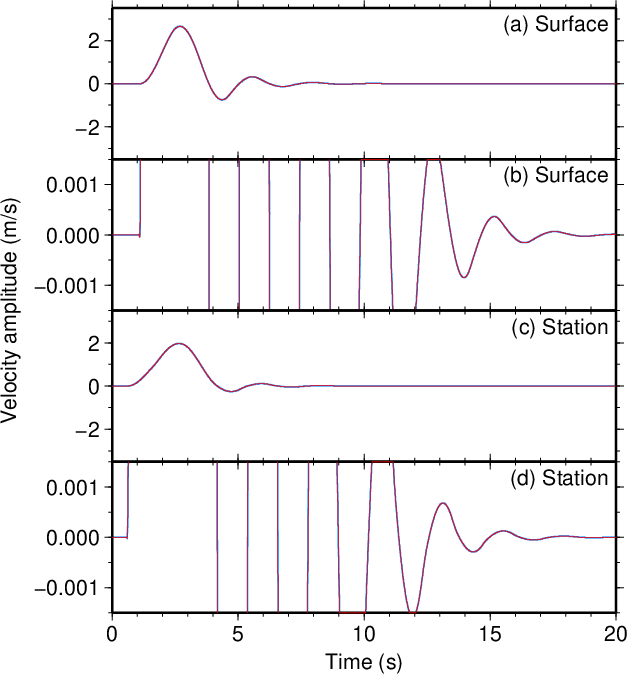
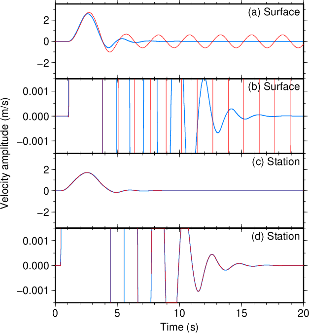
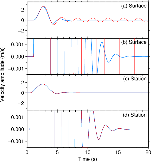
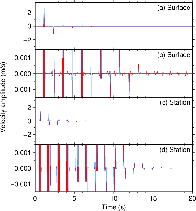
\(f(t)\)の時定数を反射波の間隔よりも十分に短い\(\tau=0.1\) sとした場合の 計算結果を図1に示す。 図の見方は均質媒質での計算と同様である。 この結果から、偽のシグナルの振幅は小さく抑えられていることが分かる。
Fig. 1 shows the result from a time constant of \(\tau=0.1\) s for \(f(t)\), which is sufficiently smaller than the interval of the reflected waves. The format of the figure is same as those in case of a uniform medium. This result indicates that the fake signal is suppressed small.


図1(Fig. 1)

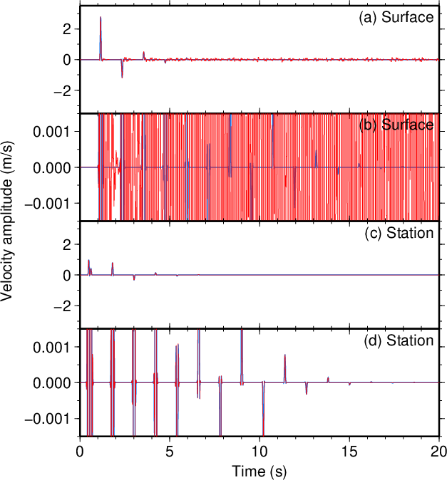
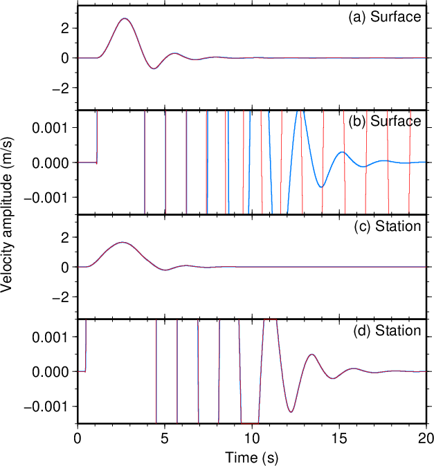
反射波の間隔よりも長い\(\tau=3.5\) sの場合の計算結果を図2に示す。 均質媒質の場合と同様、長い時定数を用いることで 偽のシグナルの振幅は更に小さくなった。
Result from \(\tau=3.5\) s which is longer than the interval of the reflected waves is shown in Fig. 2. Consistent with the case of the homogeneous medium, using a long time constant reduced the amplitude of the fake signal.


図2(Fig. 2)

なお、ボアホール観測点が層境界よりも浅部にある場合には 差分計算の対象領域内(\(-h\leq z\leq 0\))は均質媒質である。 したがって深部から多数の波群を入射させただけで 基本的には均質媒質でのテストと同等である。
Note that when the borehole station is located shallower than the layer boundary, the computational volume of the FDM calculation (\(-h\leq z\leq 0\)) is a homogeneous medium. Therefore the situation is basically same as the test in a uniform medium, except for a repeated incidence of many wave packets from depth.


2-2. ボアホール観測点が層境界よりも深部にある場合 (Borehole station deeper than the layer boundary)

次に\(h>d\)の場合を考える。 以下のテストでは\(h=1500.1\) mを用いる。 このとき観測波形は\(V_{0,u}\)、\(V_{1,d}\)、および 全ての\(n\)に対する\(V_{2n+3,d}\)を足し合わせたものとなる。 層境界とボアホール観測点の間の走時は\((h-d)/V_2\)であるので、 (\ref{eq.V_0_u.boundary}) (\ref{eq.V_1_d.boundary}) (\ref{eq.transmitted.d.boundary})式から走時分をずらすことで ボアホール観測点の位置において \[\begin{equation} V_{0,u}(-h,t)=f(t+(h-d)/V_2) \label{eq.V_0_u.station} \end{equation}\] \[\begin{equation} V_{1,d}(-h,t)=\frac{V_2-V_1}{V_2+V_1}f(t-(h-d)/V_2) \label{eq.V_1_d.station} \end{equation}\] \[\begin{eqnarray} V_{2n+3,d}(-h,t) &=& (-1)^n\frac{4V_2(V_2-V_1)^nV_1}{(V_2+V_1)^{n+2}} \nonumber \\ & & f(t-(2n+2)d/V_1-(h-d)/V_2) \label{eq.transmitted.d.station} \end{eqnarray}\] が得られる。これらを足し合わせて \[\begin{eqnarray} V(-h,t) &=& V_{0,u}(-h,t)+V_{1,d}(-h,t)+\sum_{n=0}^{\infty}V_{2n+3,d}(-h,t) \nonumber \\ &=& f(t+(h-d)/V_2)+\frac{V_2-V_1}{V_2+V_1}f(t-(h-d)/V_2) \nonumber \\ & & +\sum_{n=0}^{\infty}(-1)^n\frac{4V_2(V_2-V_1)^nV_1}{(V_2+V_1)^{n+2}} \nonumber \\ & & f(t-(2n+2)d/V_1-(h-d)/V_2) \label{eq.V.station_deep} \end{eqnarray}\] がボアホール観測点での理論波形となる。
We next consider the case for \(h>d\). In the tests below, \(h=1500.1\) m is used. In this case, the observed waveform is the summation of \(V_{0,u}\), \(V_{1,d}\), and \(V_{2n+3,d}\) for all \(n\). The travel time between the layer boundary and the borehole station is \((h-d)/V_2\). Taking into account this travel time in Eqs. (\ref{eq.V_0_u.boundary}), (\ref{eq.V_1_d.boundary}), and (\ref{eq.transmitted.d.boundary}) results in Eqs. (\ref{eq.V_0_u.station}), (\ref{eq.V_1_d.station}), and (\ref{eq.transmitted.d.station}) at the borehole station location, respectively. Taking the summation of these terms, we obtain the theoretical waveform at the borehole station given by Eq. (\ref{eq.V.station_deep}).

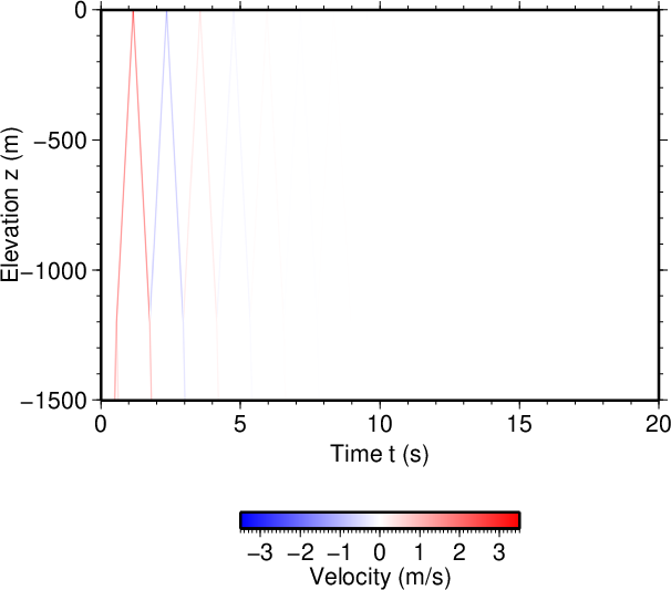
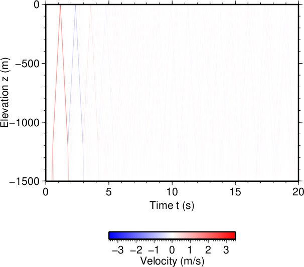
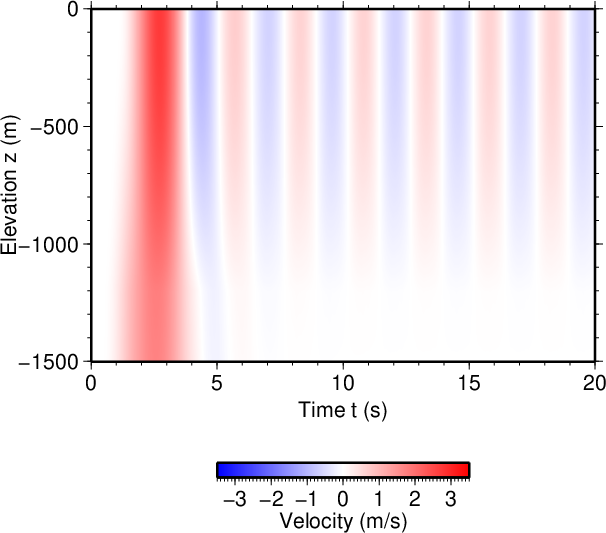
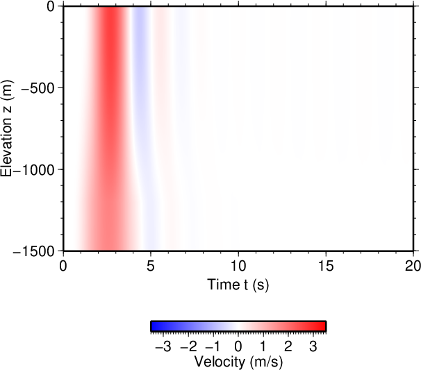
この(\ref{eq.V.station_deep})式の観測波形を用いた \(\tau=0.1\) sのときの計算結果を図3に示す。 この場合にも地表での理論波形をよく再現でき、 偽のシグナルを小さく抑えられたことが分かる。 図4にはスナップショットを示した。 層境界(\(z=-1200\) m\)において反射波が繰り返し発生していることが分かる。
The calculation result from the observed waveform of Eq. (\ref{eq.V.station_deep}) for a case of \(\tau=0.1\) s is shown in Fig. 3. The theoretical waveform at the ground surface is well reconstructed, suppressing the fake signals small. Fig. 4 shows the snapshot, indicating that reflected waves are repeatedly generated at the layer boundary (\(z=1200\) m).


図3(Fig. 3)


図4(Fig. 4)

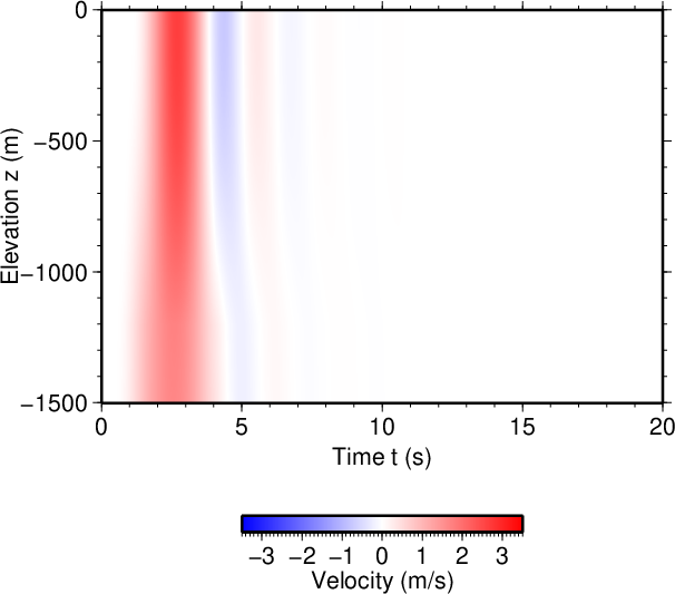
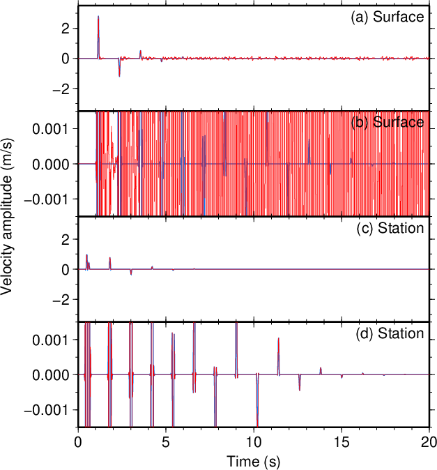
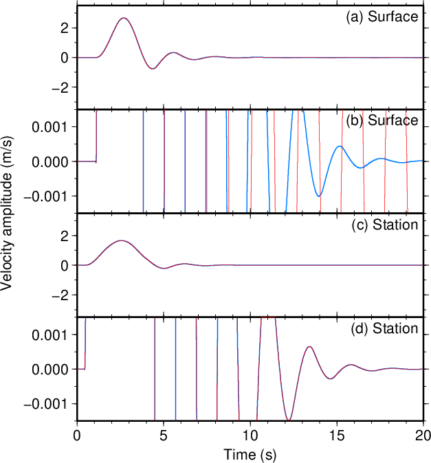
\(\tau=3.5\) sの場合の結果を図5, 図6に示す。 この場合にも時定数を長くすることで 偽のシグナルを更に小さくすることができた。
Result from \(\tau=3.5\) s is shown in Fig. 5 and 6. Using the large time constant, the fake signals became still smaller.


図5(Fig. 5)


図6(Fig. 6)


2-3. 地下構造が正しくない場合 (In case of an incorrect subsurface structure)

均質媒質の1つ目の例(1-1節)で説明したように、 ボアホール観測点での観測波形は地下から到来した上向きの波と 地表で反射した下向きの重ね合わせであり、 このうちの下向き反射波で説明できない部分がソースとなる。 このことから計算に使用する地下構造が正しくない場合には 実際の反射波と計算上の反射波が異なるものになり、 その差分が偽のソースとなって偽の波群を生じる恐れがある。 これについて検証した。
The observed waveform at the borehole station is a superposition of upgoing waves from below and downgoing waves reflected from the ground surface, and only a part of the observed waveform that is not explained by the downgoing reflected wave acts as the source, as was explained in the 1st example in section 1-1 of the uniform medium. This suggests that if the subsurface structure used in the computation is not correct, the difference between the actual and calculated reflected waves may act as an artificial source that causes a false wave packet. Tests were conducted to examine this issue.

以下のテストでは2層構造を与えて (\ref{eq.V.surface})式により地表の波形の正解を、 (\ref{eq.V.station_deep})式によりボアホール観測点の波形を生成する。 次にそのボアホール観測点の波形を入力として用いて FDM_1D_verticalコマンドにより地表の波形を計算するが、 このときには入力波形の生成時とは少しだけ異なる2層構造を使用する。 これによって得られた地表の波形を先に生成しておいた正解と比較する。
In the texts below, the correct waveform on the ground surface was created using Eq. (\ref{eq.V.surface}) and the waveform at the borehole station was created using Eq. (\ref{eq.V.station_deep}) assuming a two-layer structure. Then the waveform at the ground surface is computed by the FDM_1D_vertical command using the waveform at the borehole station as the input; in this step, a two-layer structure slightly different from what was used in generating the input waveform. The waveform on the ground surface obtained by this FDM computation is compared with the correct answer created earlier.

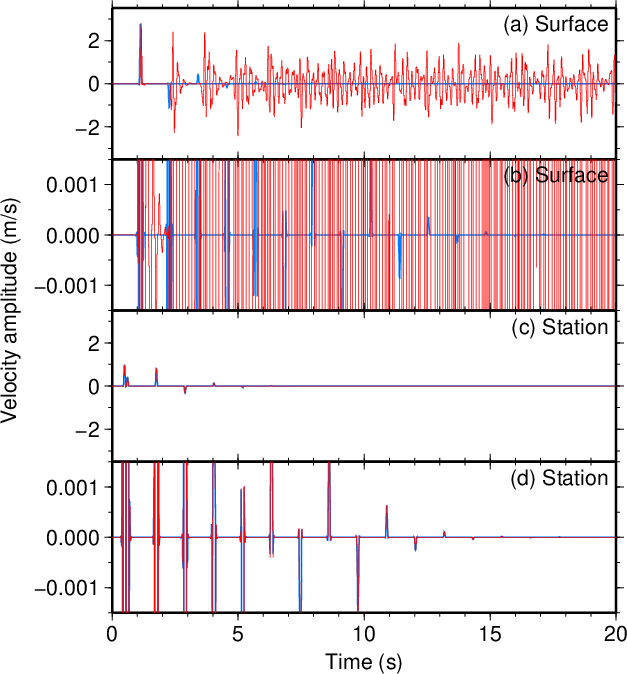
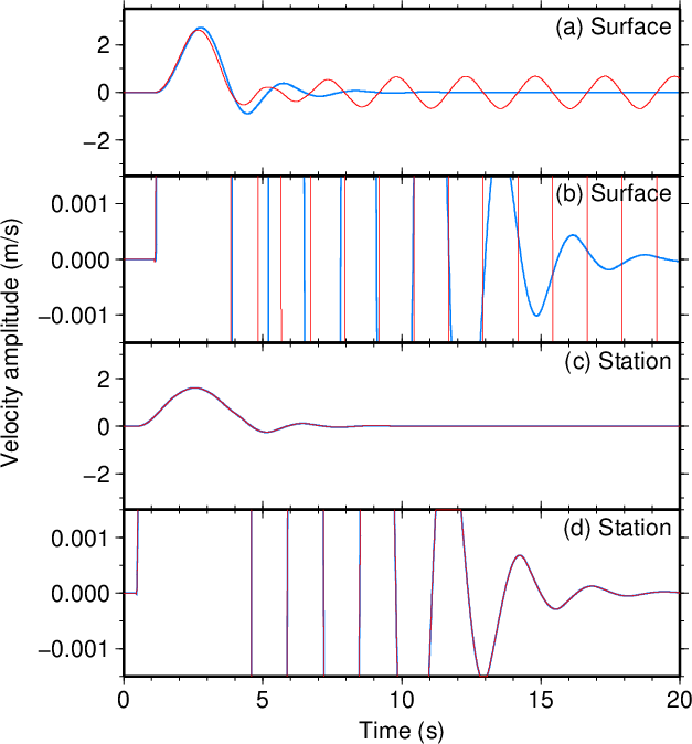
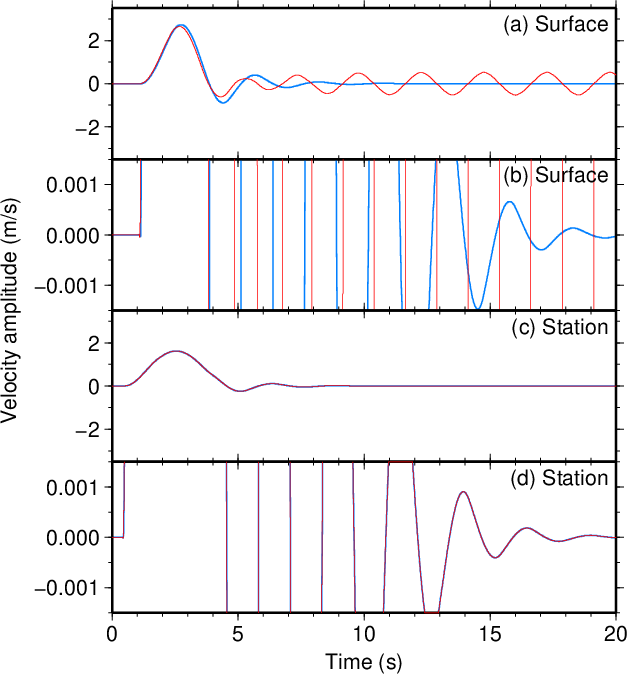
以下の全てのテストにおいて、 FDM_1D_verticalコマンドでは2-1, 2-2節と同じ構造 (第1層の厚さ\(d\sim 1200\) m, 第1層の速度\(V_1=2000\) m/s, 第2層の速度\(V_2=5000\) m/s)を使用する。 地表での波形の正解やボアホール観測点の波形の生成に用いる構造 (速度構造の正解)の方をテスト毎に変える。 \(d\)を100 mだけ小さくした場合/大きくした場合、 \(V_1\)を100 m/sだけ小さくした場合/大きくした場合、 \(V_2\)を100 m/sだけ小さくした場合/大きくした場合、 の計6通りを試す。 2-1, 2-2節にならって \(\tau=0.1\) sの場合と\(\tau=3.5\) sの場合を試すので、 テストは計12種類になる。 これらのテストで用いたパラメータを表1に、 結果を図7-22に示す。
Throughout the tests below, the same structure as that used in sections 2-1 and 2-2 (the thickness of the 1st layer \(d\sim 1200\) m, the velocity of the 1st layer \(V_1=2000\) m/s, and that of the 2nd layer \(V_2=5000\) m/s) was used. The structure for generating the correct waveform on the ground surface and the input waveform at the borehole station (the correct structure) was changed depending on tests. A total of six cases were tested, where \(d\) was decreased or increased by 100 m, \(V_1\) was decreased or increased by 100 m/s, or \(V_2\) was decreased or increased by 100 m/s. Following sections 2-1 and 2-2, \(\tau=0.1\) s and \(\tau=3.5\) were tested (thus 12 test in total). Parameters in these tests are shown in Table 1, and the results are shown in Figs. 7-22.

表1 (Table 1)

Figure
\(\tau\) [s] 正しい構造
Correct structure
差分法で用いた構造
Structure used in the FDM
\(d\) [m] \(V_1\) [m/s] \(V_2\) [m/s] \(d\) [m] \(V_1\) [m/s] \(V_2\) [m/s]
7, 8 0.1 1100 2000 5000 1200 2000 5000
9 1300 2000 5000
10 1200 1900 5000
11 1200 2100 5000
12, 13 1200 2000 4900
14 1200 2000 5100
15, 16 3.5 1100 2000 5000
17 1300 2000 5000
18 1200 1900 5000
19 1200 2100 5000
20, 21 1200 2000 4900
22 1200 2000 5100


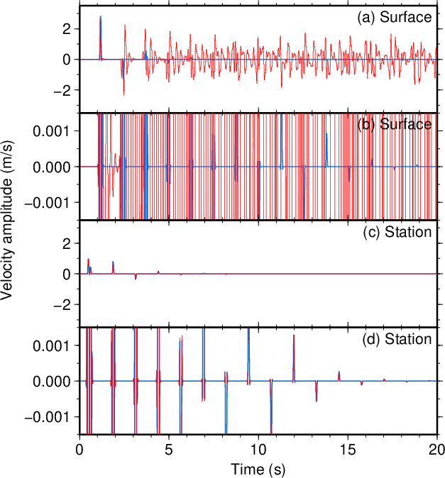
図7. \(d\)が100 mだけ小さい場合(\(\tau=0.1\) s)。
Fig. 7. Decreased \(d\) by 100 m (\(\tau=0.1\) s).


図8. \(d\)が100 mだけ小さい場合(\(\tau=0.1\) s)。
Fig. 8. Decreased \(d\) by 100 m (\(\tau=0.1\) s).


図9. \(d\)が100 mだけ大きい場合(\(\tau=0.1\) s)。
Fig. 9. Increased \(d\) by 100 m (\(\tau=0.1\) s).


図10. \(V_1\)が100 m/sだけ小さい場合(\(\tau=0.1\) s)。
Fig. 10. Decreased \(V_1\) by 100 m/s (\(\tau=0.1\) s).


図11. \(V_1\)が100 m/sだけ大きい場合(\(\tau=0.1\) s)。
Fig. 11. Increased \(V_1\) by 100 m/s (\(\tau=0.1\) s).


図12. \(V_2\)が100 m/sだけ小さい場合(\(\tau=0.1\) s)。
Fig. 12. Decreased \(V_2\) by 100 m/s (\(\tau=0.1\) s).


図13. \(V_2\)が100 m/sだけ小さい場合(\(\tau=0.1\) s)。
Fig. 13. Decreased \(V_2\) by 100 m/s (\(\tau=0.1\) s).


図14. \(V_2\)が100 m/sだけ大きい場合(\(\tau=0.1\) s)。
Fig. 14. Increased \(V_2\) by 100 m/s (\(\tau=0.1\) s).


図15. \(d\)が100 mだけ小さい場合(\(\tau=3.5\) s)。
Fig. 15. Decreased \(d\) by 100 m (\(\tau=3.5\) s).


図16. \(d\)が100 mだけ小さい場合(\(\tau=3.5\) s)。
Fig. 16. Decreased \(d\) by 100 m (\(\tau=3.5\) s).


図17. \(d\)が100 mだけ大きい場合(\(\tau=3.5\) s)。
Fig. 17. Increased \(d\) by 100 m (\(\tau=3.5\) s).


図18. \(V_1\)が100 m/sだけ小さい場合(\(\tau=3.5\) s)。
Fig. 18. Decreased \(V_1\) by 100 m/s (\(\tau=3.5\) s).


図19. \(V_1\)が100 m/sだけ大きい場合(\(\tau=3.5\) s)。
Fig. 19. Increased \(V_1\) by 100 m/s (\(\tau=3.5\) s).


図20. \(V_2\)が100 m/sだけ小さい場合(\(\tau=3.5\) s)。
Fig. 20. Decreased \(V_2\) by 100 m/s (\(\tau=3.5\) s).


図21. \(V_2\)が100 m/sだけ小さい場合(\(\tau=3.5\) s)。
Fig. 21. Decreased \(V_2\) by 100 m/s (\(\tau=3.5\) s).


図22. \(V_2\)が100 m/sだけ大きい場合(\(\tau=3.5\) s)。
Fig. 22. Increased \(V_2\) by 100 m/s (\(\tau=3.5\) s).

予想された通り、 真の反射波と計算で出てくる反射波の不一致がソースとなって 後続波部分に大振幅かつ永続する振動を生じている。 なお今回のテストの範囲では\(V_2\)を動かした場合の影響は比較的小さくなった。
As was expected, the inconsistency between the actual and simulated reflection waves acted as a source to generate large and long-lasting oscillation in a later portion. Within the tests conducted, the effect of \(V_2\) was relatively small.